my bench

Finally after all these years, I've  actually got round to  starting my new bench. It's always been on my To-do list but as many of you will know when as you go through your married life,  mortgage,  kids car repairs you know the usual, a luxury like a cabinet makers bench just gets shoved to one side.

offcuts left for  tail vices etc
First I'll tell you a little about the bench I intend to make, I want to keep it as traditional as possible, but, with a difference, I am in desperate need of tool storage space and extra vices fitted.

I like to work around my bench from both sides and from the ends at times depending on what I'm working on. I've been pondering different the designer bench now for some time  My bench will be sort of a Heinz 57 the version of some ideas pinched from them all with a few ideas of my own worked into the build as it progresses.

The new bench  will have two York (tail vices) and one York shoulder vice, a line of dog holes along both edges and possibly other dogs hole  across the benchtop for cramping purposes.

This morning I made a start and machined the core for the top, the pieces are temporarily clamped together overnight.

core boards cut  marked for biscuits
I decided to build the top from American Oak ( just my choice)  no other reason,  with a softwood base (still to be sourced), the carcase for the tools stowage to be made out of 18mm and drawers from 12mm  birch ply.

Last week  I sourced some nice American  Oak pieces  2  @ 3.6m x 195mm x 80mm   plenty enough to make the top from, overall sizes approximately  2m x 600mm  with the core of the top is 50mm thick,  the edged skirt  somewhere about 70mm to give that  extra thick look, the oak arrived yesterday.

waiting for  assemble

I  ordered the ironwork from Axminster tools for the bench,  as mentioned above but these are out of stock till next week, but, that's not the problem at the moment for me.

biscuits glued and waiting for assemble

25/11/2012    End of day today all 264 biscuits cut machined out and ready for glueing,  I only have eight sash cramps, so I'm going to glue  the core boards up  in pairs  when I have  three pairs  all glued then I will glue  the first pair and second pair together, when they're set, I'll glue the last pair to the first four boards this then forms the  main core to the benchtop.

1st boards glued
Please note,  the biscuits cuts to  the outer edge of the 1st boards  this will be to glue the skirts around the main benchtop core to house the dog holes, this I will deal with later in the thread.

26/11/2012   
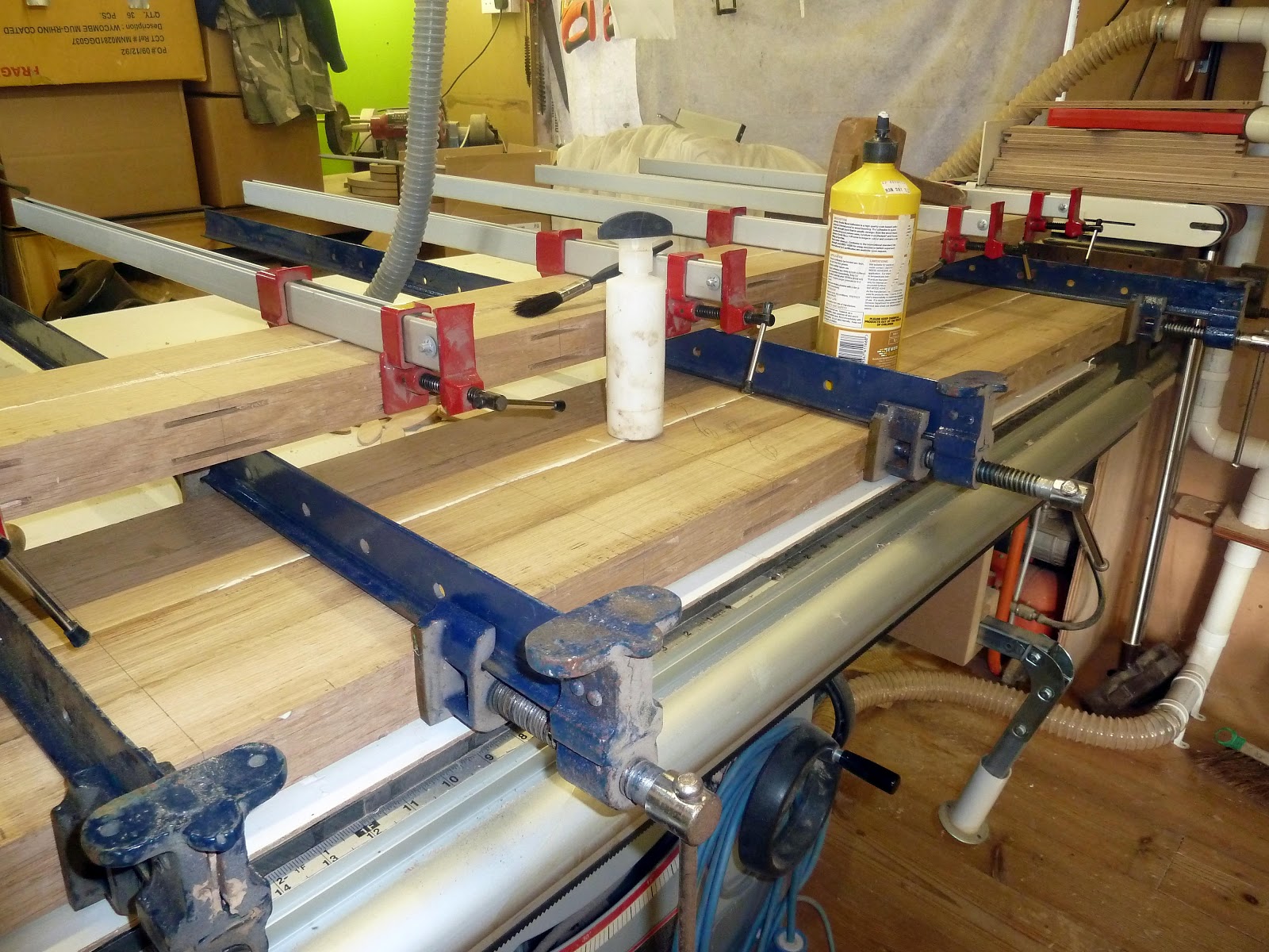
Showing in the foreground the second pair just glued up  on top yesterdays pair in the background the last pair later today or early tomorrow maybe, 22 biscuits in a double row it takes quite a lot of the pressure to cramping these together.


27/11/2012   As seen above  the  final pair of core boards now glue together plus day 1 and 2  also tomorrow the final glueing to the core boards.

I'm not going to  machine the  core top  to its final finished level  yet till it's fixed to the base unit, I'll deal with that later in this thread. Tomorrow I'll start machining the side  skirt boards for the  dog holes etc. 

First casualty today oops,  as seen in the above last photo    just giving that extra squeeze   in the final cramping and  ping, totally knackered one of a set of eight, bummer Grr. 

28/11/2012   Today another casualty  a second clamp broke not one of  those I used yesterday  but one of the heavy-duty cast-iron one as used in the lower the picture  suddenly a chunk of cast iron flew  off t the back end of the shoe, it's still usable  as yet not sure how badly damaged  the clamp is till I remove it tomorrow. 

All the core board to the top are now glued together,  remove clamps tomorrow and  start  a cutting list for the skirt and  various parts for the vices, got an email today  telling  there's a three-week wait for the ironmonger on all three vices, now that could be a nuisance. 


01/12/2012  Today, ooh... it was colder in the workshop this morning than it was outside, I waiting for a few hours till the sun moved around and warmed things up a bit still cold in the workshop but not so bad when you got going. Machined the side skirts and boards for the dog hole.      02/12/2012  I machined the side skirt today, cut all mitres and machined a load more biscuit cuts, ended the day with a dry dummy run fitting the skirt boards to one side of the bench. I machined out the groove for the tail vice guide.

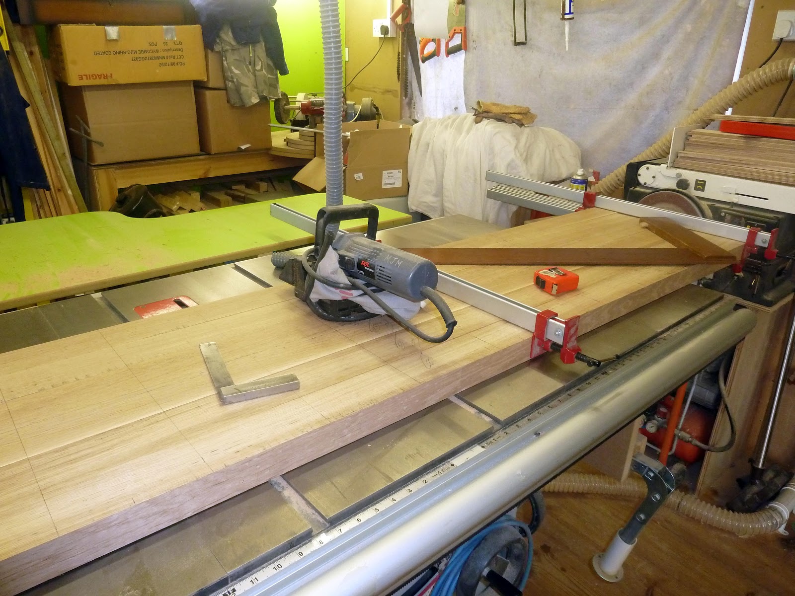
 05/12/2012 Dry run with both side skirts fitted. Finally arrived aboard a slow boat from china the ironwork for the three vices that will be fitted two-tail vices and one shoulder vice for ease of use from all four sides of the bench.


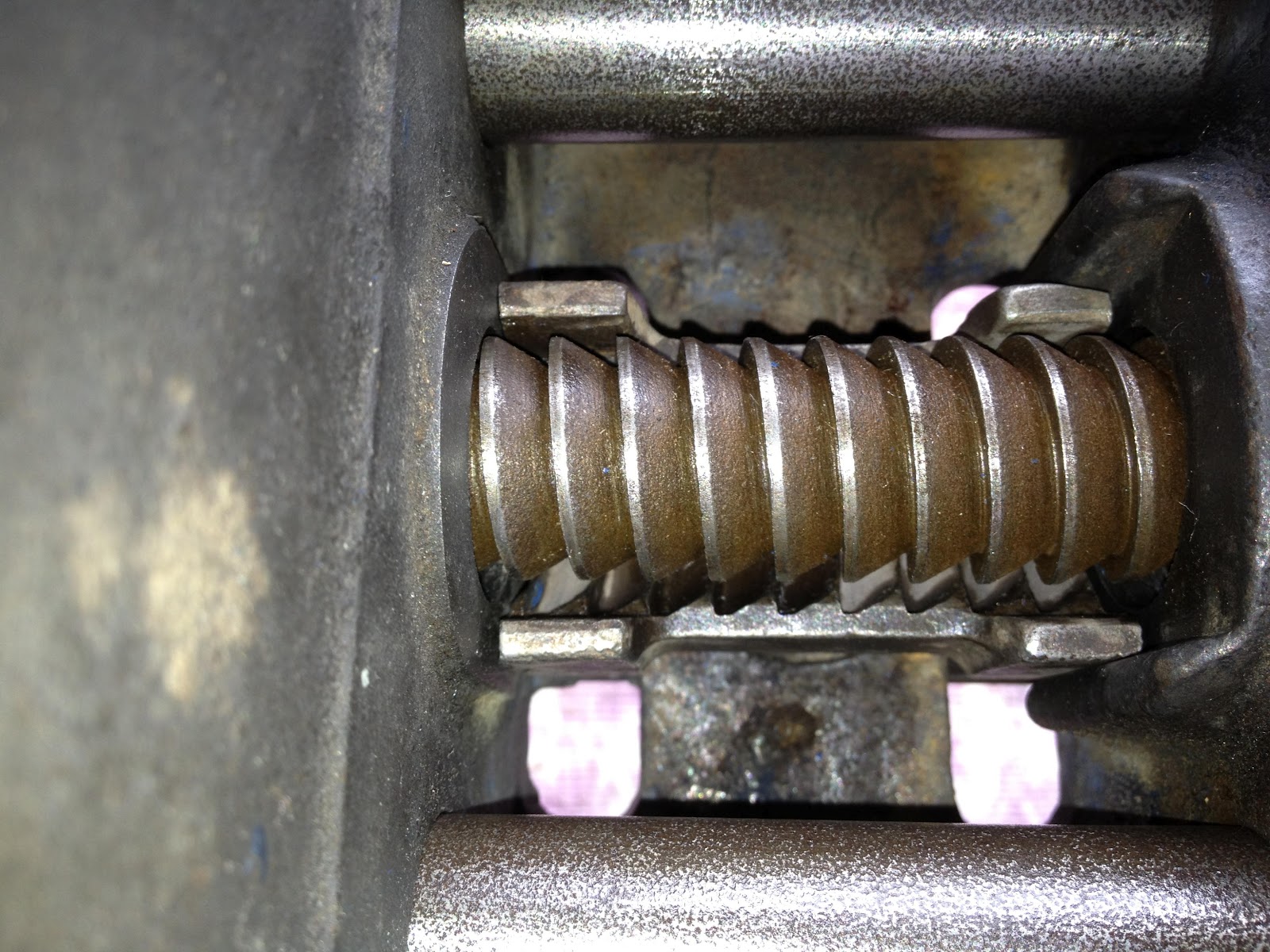
Here are both the  York tail vice. I have never fitted one of these so I had better do some research first It's  quite a complicated vice to manufacture and assemble, although fitting the ironwork I think should be straight forwards enough.

The Chinese engineering on these thread screws are to a very high standard I'm very impressed with them. Next to follow a shoulder vice  screw thread again never fitted one but I feel it's a straight forwards to fit as well.

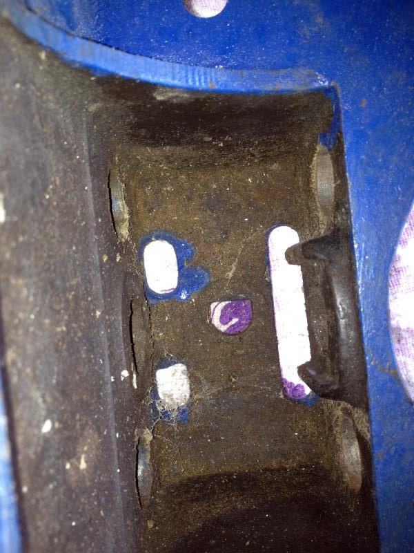
Also ordered at the same time some bed furniture bolts which the photo explains what they're intended for.

Ok, it's back to the workshop this afternoon after the Christmas and new year festivities.

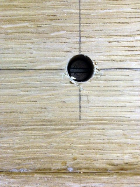
I made as start  as seen in the above  photo on the bed bolts to hold the  oak  carrier that will  do several things really ie to help hold the benchtop flat when fully glued, its primary use is to form part of the vice on the corner of the bench,   as seen in the  last photo  it still  only a dummy run,  those four biscuits  will be fitted  above the four bolts when all is glued together I used the same centre line  to line everything up nicely.   I'll  start on the same piece on the other end of the bench tomorrow.

As you can also see from the last photo  the oak carrier has been left long, the reason being that the end will also form part of the  tail vice itself, it will have a tenon cut onto it  which will be  running through a groove  to help slide and hold in place the tail vice at the correct level/height to the bench top,  (more on that later in the thread.)


refurbing my other vice

My second vice is a record 52 1/2 in the same sort of condition as the other vice.


Before I make a start I want to show you all that I meant by the statement I made in my previous post.

Most of the cleaning is either old grease someone used in the past or oil and dried sawdust which time clogs up the drive threads making it difficult to use your vice.


When I stripped this vice, I was shocked at what I found best described as years of neglect see for your selves. I have clean out the top two thread in the clutch housing just so you can see the thickness of grease and sawdust that has clogged up the clutch over the years making it very difficult to disengage the clutch to open or close the vice.

The clutch housing on this vice is enclosed, making it a poor design IMHO,  all the sawdust gathers inside and it gets stiffer to use the last owner just kept adding oil to make it work again, After a time the oils and sawdust become crusted, hence why it now left soaking in white sprites to soften till next week. In the meantime over the weekend start to clean the rest of the vice.

The re-build. Am I glad that all the cleaning is now done, the clutch housing design made it extremely difficult to clean out, it was very time consuming, don't want to do that again? Anyway, it's done now.

Here we see on the left all part cleaned, central the clutch actual now it has a spline, right looking into the clutch housing.

I made reference in the other vice thread as to what was the difference between the  52/1/2e and the 52 1/2  that if you knew to let me know, well now I can tell you now.

The  52/1/2 has a manual hand operated quick release lever, the 52 1/2E has an automatic hand operated quick release lever, i.e. with the quick release lever move it to the left and the clutch disengages release the lever it springs automatically back to the right and the clutch automatically re-engages locking the clutch on the spline.

With this vice52/1/2 you have to move the lever to the left to disengages the clutch and that is all that happens, to re-engage the clutch onto the spline you have to move manually the quick release lever back to the right to lock the spline, to re-engage the clutch onto the spline.


Left, vice reassembled looking into the enclosed clutch housing, when the lever is moved to the left the clutch has disengaged from the spline, middle to lock spine move lever back to the right as seen here with the clutch re-engaged onto the spline.  Right vice now assembled and ready for painting, Now all you need to do is replace split pin the end of spline your vice is now completed.

In conclusion.

The record 52/1/2  is obviously the forerunner to the 52 1/2E Now having refurbished the two vices which IMHO  is the better of the two vices, with any doubt at all it's the 52 1/2E  with its automatic quick-release lever. The latter vice being a revamped version which is a much-improved version and far superior vice in all aspects.

Being a professional joiner I have always used the quick release vices and now after refurbishing a manual vice and seeing how it all works inside  I can't see myself working with one automatic vice and one manual vice fitted to the same bench.

The 52 1/2, I intensely dislike the enclosed clutch housing on it.  I  don't like the manual lever at all and the way it's assembled inside the clutch housing, I suppose for someone say a DIY er or the occasional weekend worker yes it would be fine for them, but not for me, ah well nothing ventured nothing gained.  enjoy. 


Refurbishing my bench vices 52 1/2E

Well here I go again, my vices both are records, one is  52 1/2E the other is also a record 52 1/2 Slightly different in the shape design, but that's all I can see unless you know different, I 'de be interested to know what the difference is if any.

I'm refurbishing these now prior to starting my new workbench.


Here they are the one in the foreground Is already stripped apart. It's a straight forward strip, first you knock out the split pin at the end of the turn screw central bar, then remove two a small bolt that hold the thumb quick release lever in place and slide it all apart, ready for cleaning and refurbishment.

Most of the cleaning is either old grease someone used in the past, or oil and dried sawdust which over time clogs up the drive threads making it difficult to use your vice but, as seen in the above photo the glide rods are rusted up and this definitely needs cleaning off, it's so when you use the thumb quick release lever to open your vice it will glide out and you don't end up having to tug struggling to pull it out.


Here are all the components cleaned up and lightly sprayed with WD40 to keep the rust off while I spray on the first primer coat to the main framework of this vice.

Primarily  an important part of the vice is the back half of it, the part that bolted under the bench and out of sight and forgotten about, really it's the vices gearbox and should be taken good care of. as seen here. With a refurbishment, this is the most important part from here on, the six holes must be bare metal, ie: no oil, grease mucky sawdust and definitely no paint.

How many of you have actually checked on this, especially if it,s been bought second hand probably it's been slapped all over with paint, then and a ton of oil and grease splattered all over to get it to work somewhere near how it should be.


Another most important part shown left above here with the aid of two pencils, these are two machined faces where the clutch site snugly between, also to be kept as bare metal, Once these and the holes are all cleaned you are now ready to do a partial rebuild. Before you go mad and totally rebuild your vice now assemble it to this stage only.

.

Just place the end spacer bar (blue) on the ends of the glide bars to hold them parallel to each other, do not refit the spacer washer and split pin.

Now leaving the front end of the vice on the bench with your right hand pick up the end with the spacer bar attached to about a thirty 30 angle keeping you left hand out of the way the back half of the vice should now slide smoothly to full length of the glide bars under it's on weight. if it doesn't then more cleaning is still required.

I have used a piece of wood to demo this but as you see the vice has to slide the full length under its own weight without assistants.

At this stage, both glide bars and holes are perfect so on to the rebuild of the clutch. The clutch while it's engaged you can only wind the vice in or out by hand, disengaged the clutch using the lever, As you engage the lever it raises the clutch off of the main screw bar allowing you to pull it open, or push closed, when you release the lever the clutch re-engages stopping you pushing or pulling any further.As seen here.

Here left in the photos shows the screw bar with the clutch sat snugly in the spiral screw, While in this position the clutch is engaged.
Middle the clutch is fully assembled and engaged note the flat bar is horizontal the pencils are showing the amount of metal shown above there points.
 
Here right, I am engaging the lever although it difficult to see in the photo the flat bar is raised on the edge nearest to you, but you can now see extra metal showing above the pencil tips, now the clutch is disengaged, and raised by a good 5 - 6mm, giving the clearance for the spiral thread to allow you to pull open the vice or close it.


Ok, clutch sat in its housing with the spiral thread underneath waiting for the main clutch housing to be bolted over it. Right looking straight on the end of the vice here you see the clutch housing bolted on, the end of the flat bar is in the horizontal position (clutch engaged) the left side of the bar is inset into the side of the shaft on the clutch which when the lever is engaged lifts the clutch, disengaging it, but, (NOTE) on the right side a finger of metal that is part of the clutch housing and must be under the flat bar this stops the flat bar from turning downwards thus giving the left side of the bar greater lift to disengage.


The assemble of the clutch housing, this is fiddly, bear in mine the lever has to be in about the 2 O clock position when the vice is in it's the normal working position, when you move the lever to the 2 0 clock position it's now under pressure from the return spring situated on the rear of the face of the vice.

Now you have to hold that pressure while at the same time as your assembling the clutch housing trying to get it over the clutch shaft and at the same time getting that finger of metal under the flat bar It's difficult it's fiddly but can be done, you may need two pair of hand and it may take several attempts, you will swear at it to get it into the right place and bolted back together, good luck.

Now you can fit the two spacing washer and split pin, you are now completed.

Just to prove it does run smoothly, blink and you will miss it. here  There you go, one down one to go.

 It's now painted and finished.


Enjoy. 

Pillar drill table

Time to get this table finished, I started this back last year, Before I went into hospital in October. Well, I'm now back to near normal as I can get.

First I cut three sections of MDF  board to form the base but I'm not sure yet if  I'm going to use the third piece, still pondering a few ideas that I want to try to incorporate into the base.  Anyway here is the radial arm drill I bought from Axminster earlier.


First I placed the round cast iron table on top of one layer of the MDF  drew around it and marked all the slots, then drill two holes through the MDF then counter bored them to recessed them to the depth of the bolt heads and fixed the first layer to the swivel head as seen.

The top layer  I simple screwed to the bottom layer from underneath, I then machined in grooves for two tee tracks which I bought from Rutland along with a kit of tee bolts and handles. I  then made the fence with elongated slots cut into them made from an offcut of Bali, this allows the fence to be tightened and secured at any angle using the drill tip as the centre spot.


My pillar drill is situated very close to the workshop door that in its self is not a problem when I'm using the drill, but when it's not in use with the MDF table attached it protrudes out into the doors entry space too much and makes life difficult entering or leaving the workshop. 

I designed this to stay attached to the circular cast iron table all the times. 

To get over this I simple unlock the table with the lever lock arms as seen on the left, the radial arm can now swing the table to the left at the same time the table swivels in the radial arm itself. as seen in the photo on the right.  I then cut a recess along the back edge of the table to allow it to fold further back ( middle photo).  Shown on the right tuck away neatly when not in use.


This now leaves me pondering, As I mentioned earlier a third layer of  MDF this would be slipped in between the two-layer to incorporate some more ideas that  I want to use with this drill or to change the design underneath completely to give the table much more depth. 

More to follow.