This post will consist of six parts .
1 The turntables. (triple) completed.
2 The bridge and universal tool rest. completed.
3 The jigs. completed.
4 Planer blades grinding set up.
5 Planer blades Honing Jig.
6 Scary sharpening.
Turntables.
The main grinders will consist of two grinders, 1. Creusen NS5125 T which includes a wet-stone to cover all grinding for chisels and plane irons, (note) not the final honing/sharpening. 2. a small Power devil set up with a wire brush on one side and a buffing pad on the other side.
The turntables (triple) will be situated in an area of 800mm, hmm, I hear you say he's gone nuts, hmm maybe I am, The second machine will be mounted off centre on the third turntable for two reasons, sorry guys you'll have to read on to find out why.
I have a Dakota planer knife sharpener it will be fitted to the left-hand bench of the workstation. The right-hand bench will be used for all my Scary Sharpening
Workshop Heaven. I use this system for ease of use to get exact cutting angles correct each and every time.
The
corner workstation bench the Creusen wet-grinder and the small Power devil.
I intend to add new jigs to the right-hand wet-stone that are similar to the tormex system. The Ceusen as seen
here when I refurbished it early in the year. I have purchased veritas grinding jig from
Axminster for use on the smaller 150mm left-hand dry stone grinding wheel.
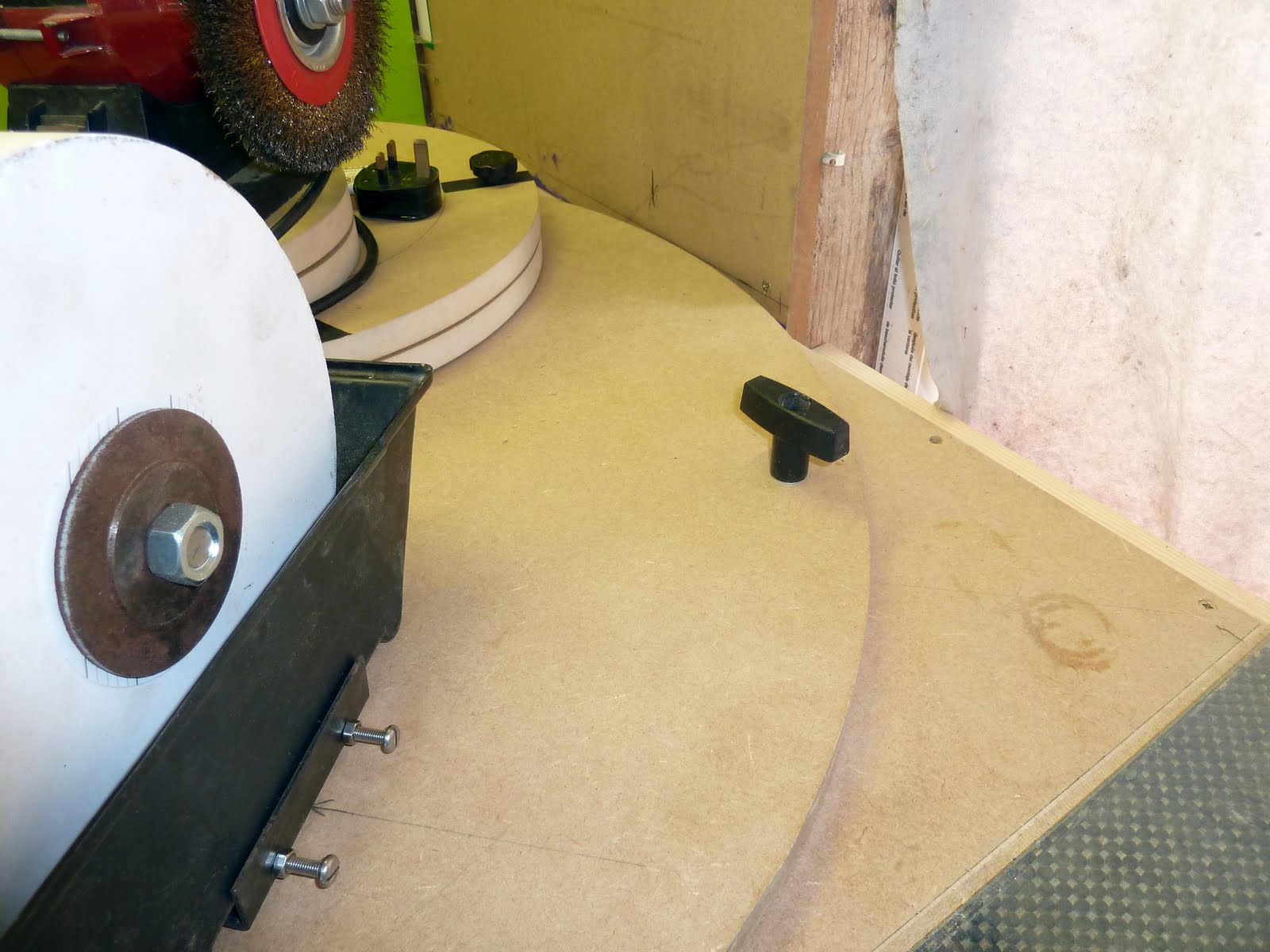
The washer spacer in the middle is approximately 2mm thick, I wanted to bolt the Creusen to the MDF I did not want to rely on screws to hold it fast, I ground the heads on four coach bolts to just under 2mm thick as seen in Photos so they would not interfere with the easy glide of the turntable.


Photos showing coach bolts driven into the underside of the top section, cradle to hold water bath, turntable reassembled, plus locking bolt fitted.
The wet-stone fitted so now I can take accurate measurements to work out the height and spacing required for the manufacture and fitting of jigs.


Seen here on the left 150mm wheel for quick fast grinding assembled with a veritas jig for plane irons and chisels etc.
On the right with a 200mm wet-stone fitted and shown turned ready for easy access to the side of the wet- stone more on this later.
Next, I cut the disc for the turntables machined the ball bearing channels and assembled them.
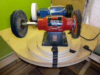
Below Left. The Cruesen in its main working position.
Middle. Turned at a 90-degree angle, drill sharpening Jig on order also showing the two new turntables with the Power devil fitted off the centre of the small turntable which will be made clearer very soon.
Right. Turned at 180 degrees with the Power devil mounted in its position for smaller pieces to be polished etc, all indication marks lined up and the securing bolt dropped into it retaining hole to lock the turntable in it's required position


It's seen more clearly here below, now, turn the top turntable about 30 degrees to the right and lock it, shown in front of the machine, all three turntables are now locked and the buffing wheel is now swung out over the edge of the workbench giving you access to buffing longer or irregular shaped items, hence why I set it off centre on the third turntable.


Switching back to the Creusen just reverse the operation, the third photo on the right above showing turning handle just crab holds, I fitted two of these ones each side on the base turntable pulls or push in either direction, I did this because with glass sheeting fitted on both side benches right up to the circumference of the turntable, whilst turning I kept catching my finger on the edges of the glass, ouch!! not nice.
I am really chuffed with the way this sharpening workstation is coming together, in particular, the way the two grinders revolve around each other in a space of less than 800mm square, neat use of space.
The bridge and universal tool rest.
The jigs for the wet-stone are along the lines of the Tormek universal support toolbars, I bought two support holders to attach my jigs earlier in the year, I had hoped I could self tap then straight on top of the Creusen but, the metal casing on the Creusen proved to be too flimsy allowing too much flexible movement and the pre-drilled hole in the support tool holders were in the wrong places.
Next, I built a bridge to go over the gearing housing in two parts, I built this from off-cut on ply, the main support pillar was just glued and pinned together with the vertical holder screwed to it, this pillar is fitted at the rear of the Creusen next to the water bath, I secured this with just one screw for now as when the universal arms are made and fitted they will need squaring with the outside edge of the wet-stone, I will then secure the main support pillar with two other screws. (more later)
Below, The main support pillar showing at the base on the left a screw hole to act as a swivel screw until the universal tool rest is fitted and squared with the edge of the water stone then secure in position with right-hand screw holes. Middle, Support pillar with vertical tool holder secured and base screwed in position. Right, Showing bridge over the Creusen gearing housing and horizontal tool holder fitted, this also has to be squared (same as the rear) when both front and rear universal tool rest holders are squared with the wet-stone then screw both front and back sections together via the bridging plywood locking front and back together all is now secured and solid.


The only downside of the ply bridge over not being able to screw straight to the cruesen is the universal tool rest is now slightly higher up the side of the wheel than I would have liked but, I feel this is not going to be a problem, only time will tell on that one.
Next the preparation for the universal tool rest, I refused to pay some £37.00 for each tool rest with just over 24 " of silver steel to each rest. These tool rest must be absolutely square with no twist in them. I decided to make a rough form-work to hold all the steels while it was being welded.


Now finished the universal toolbars in their holders its beginning to take shape, before I finally decide on what types of setting tool jigs I intend on using, down to Axminster next week to have a look at some of there setting tools. I am contemplating extending the toolbars around and along the edge of the wet-stone hence why I have left them long for the moment.
As shown here Both Universal tool Bars welded and fitted, The more time spent here now fiddling the better, they must be 100 per cent spot-on square to the grinding wheel, this applies to both tool rests front and back, It's most important and will prove time well spent in the end.
I mentioned earlier in the post the swivel screw, now it time to lock the tool rest square to the grinding wheel. You need a large square you know you can trust, Now just simple place the square on the tool rest as shown twist the pillar arm till the square touches it entire length along the edge of the grinding wheel (as shown) and screw in the locking screws, now repeat on the front jig and lock it as well. with this is done, screw the bridge on top and lock the two together, done.


As seen above on the left, bars to be shortened to come inside the sweep of the circumference on the base turntable to clear the corner wall as it swivels so they can be left on the machine at all times.
Finally below, looking from the front through to the back tool rest you see both are square and there is no twist in the bars both run level and both run parallel with each other, I want to design another toolbar along the side of the grinding wheel but at a lower level, maybe connecting with both front and rear tool bars but, first a trip to Axminster Tools, just to dot a few Is and cross a few Ts in my mind's eye.

Once I am sure it will all connect up as I want the tools bars to, then that will cover all the different styles of wet-stone grinding that I need from plane blades to chisels gouges scissors etc plus all my turning tools as well.
updated
Well, I thought now that the universal tool rest was fitted it would straight forwards get the jigs that I required and away we go, oops I soon found out, not so.
I set up my first jig, I am going to grind all my hand plane blades and most of my chisels from the side of the stone, To be honest, I'm not really a big fan of hollow grinding although I will if I have to, While I was dressing the stone I noticed an amount of flex in the front and rear universal tool rests which for me was unacceptable with just the weight of my hand resting on the end of the steel 12mm rod you can see it flex , I know at the moment they are longer than required but, even when shortened to there final length they will still flex.
This has forced me to rethink the way I want to set up my jigs, I want to eliminate all flexibility in the tool rest, I now know when I originally dressed the edge of the wet- stone the bar was flexing with every turn of the screw meaning the stone is not perfectly square, getting fussy in my old age.
Left, original dressing in progress. Middle, cross side toolbar for plane blade jig to hang from, it is to short it needs to be longer and cross over the front toolbar for more support plus it needs to be locked into place to stop any sideways or vertical waggle when under pressure from movement. Right planer jig hanging on the toolbar set up to grind at 25 degrees more on setting the angles later.


The next problem I have is to get a longer cross over side toolbar which are not made to the length I require.
As yet I don't have a metal workers lath only my trusty old M950 Axminster so, I thought I would have a dummy run on a short offcut of steel bar I had leftover. I really surprised myself here with the results.
Now I'm not condoning anyone should try doing it this way, in fact, don't unless you feel really comfortable with your tools and your own abilities. Bear in mind this was machined using tools like a junior hacksaw to cut the shoulders and several different files to machine file it down to the right diameters required and an 8mm thread cutter and that's it with the lathe set at the slowest possible speed.
Left, shop-bought cross side toolbar, the two-part screwed together. Middle, two-part separated showing shoulders required. Right, My attempt using the tools mentioned above, done myself proud I think by any standards, not so good as if it had been done on a metalworking lathe but, still acceptable compare middle photo to the right photo.
Now tomorrow get some longer 12mm silver steel and start all over again.


Phew, that took some doing preparing the second one, anyway, it's now done, Must get myself a small metal workers lathe it would make life so much easier, so OK onwards.
Next, before I go mad and start slapping jigs on it all over the place it time first to check all three toolbars are level. I cut and shaped two toolbar pillar supports from oak, these are to support the end of the bars to stop any flexing downwards movements and small pillar support sandwiched between the front bar and the side crossover toolbar secured as seen in the photo, it just snaps into position.


Seen here the bars pillar support, they simply slip under the bars and lock into the half-cut 12mm hole to stop any downward movements. To fit the plane blade jig simple slacken the two locking hand nuts located on the rear bar and lift the front end of the sidebar, simply slip on the jig with a blade attached to it, push down and it clips into the small pillar support then lock the two hand nuts now grind your blade.


Now that's the universal toolbars are fitted I'm more than happy with the amount of bar flexibility the pillar supports have removed, excellent, the bars are also cut to length and finished, the whole turntable can now be revolved around 360 degrees without removing any of the toolbars or jigs.
The Jigs.
OK here are the jigs that I already have and the link to another that I still need to get.


I decided to buy the Tormex turning tool setter jig and the Tormex angle master jig solely to be able to set up the angles for chisel whether it was for wood chisels, or turning chisel, with all there various angles to get them correct each and every time + also for the plane blades for the same reason to be able to get the angles set very quickly and accurately for all of my cutting edge tools.
I still have to get the Tormex
multi jig . all other jigs after that will be nice to have but, only when finances allow.